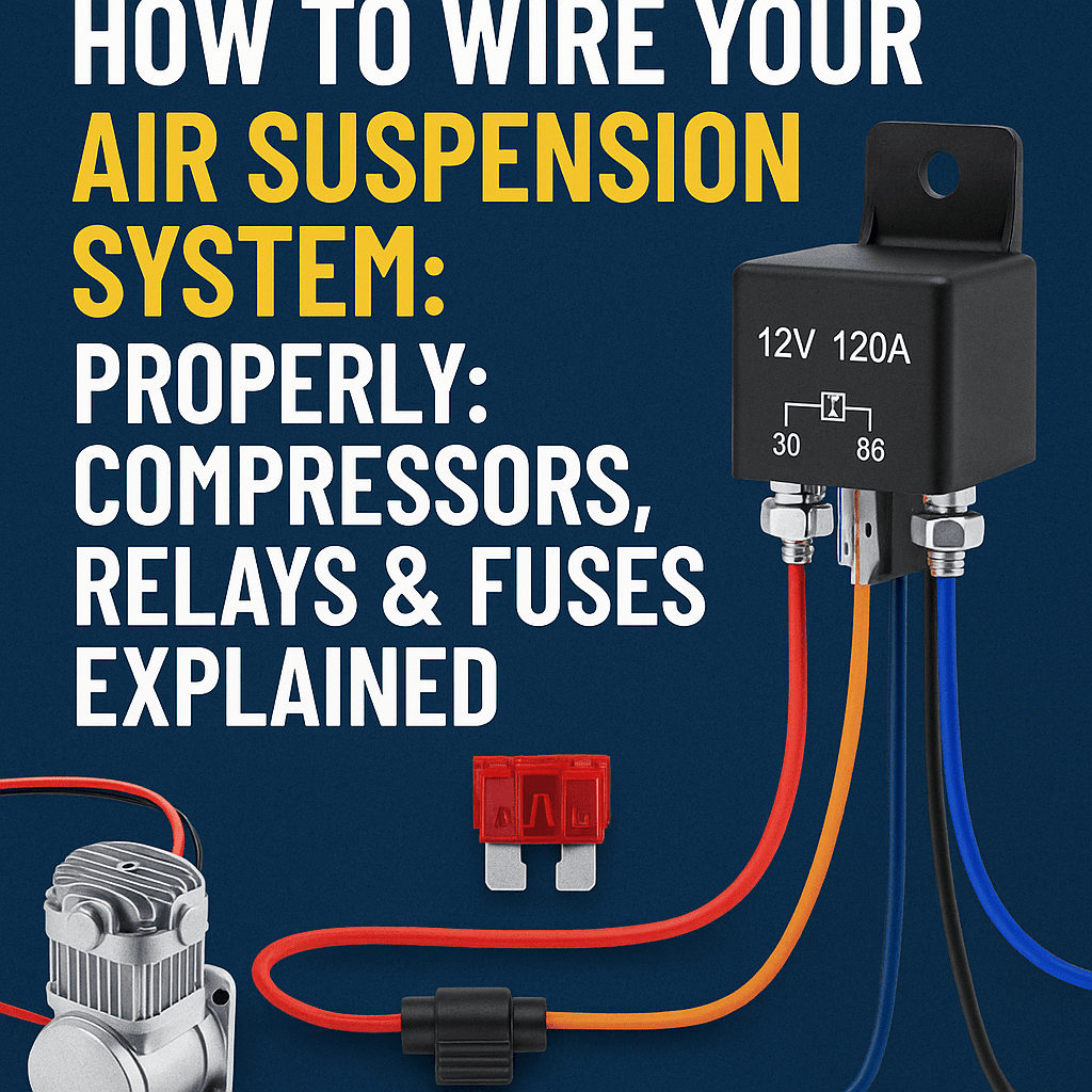
A wiring plan must match the actual compressor and management equipment. A generic wire-gauge or relay-pin chart is not a substitute for the supplied wiring diagrams.
Start with the component instructions
Confirm supply voltage, current requirements, recommended fuse protection and the compressor’s duty limits. Check the relay’s current rating and its own pin diagram, including any polarity-sensitive suppression components.
Size each circuit correctly
Wire size depends on current, total circuit length, acceptable voltage drop and installation conditions. Use suitable stranded automotive wire and protected routing. Do not choose a fuse larger than the wire and component instructions permit.
Protect compressor power
Plan separate protection for each compressor and place circuit protection according to the component instructions. The management controller must not carry compressor motor current unless explicitly designed for that purpose.
Ground and route deliberately
Follow the supplied grounding arrangement. Keep high-current motor wiring and sensitive signal wiring routed appropriately. Use secure terminations and protect against abrasion, heat and moving parts.
Inspect before energizing
Have polarity, fuse selection and connections checked. Melted insulation, an overheated connection or recurring fuse failures need diagnosis before reuse; tape does not restore damaged wiring.
Get equipment-specific wiring help · View current compressor models
KEEP LEARNING.

Classic VW Beetle on Air: Custom Frunk | ONAIR x Lukaszsports
Lukaszsports x ONAIR bring a classic Volkswagen Beetle to the ground with a custom-fabricated frunk, 4-gallon seamless tank, VIAIR compressor...

2019 Volkswagen Golf Alltrack on Air | ONAIR x ADE Creations
A bagged 2019 Volkswagen Golf Alltrack featuring ONAIR performance air suspension, a fully hidden dual-compressor 4V setup and an ADE...

Air Ride in a Canadian Winter: The ONAIR Maintenance Guide
Air ride can handle Canadian winters. Get ONAIR's 60-second checklist, moisture-draining tips, extreme-cold antifreeze guidance and an easy winter care...
FROM ARTICLE TO AIR RIDE
BUILD THE COMPLETE SYSTEM.
Ready to put the pieces together? Build your ONAIR setup step by step and keep the whole package in one place.
Build Your ONAIR Kit